


The M14 and M1A rifles do not normally have a Picatinny rail. They're not quite built for easy installation of a scope by other means, either. Still, these rifles are not without hope in the field of attached optics. Using the existing architecture of the rifle, it's possible to attach all the mounting equipment necessary to install a rail.
In this article, we'll take a look at how to install the M14/M1A rail kit, and some of the common concerns about rails on these sorts of rifles.
Kit Contents

- Clip guide replacement
- Set screw
- Set screw
- Adjustment bushing
- Windage set screws
- Bracket mounting screw
- Front bracket
- Set screw
- Set screw
- Small set screw
- Picatinny rail
- Rail attachment screws
- Ejection port guide
The M14/M1A kit contains a handful of screws, set screws, and steel parts. Ignoring the screws, we have four main pieces:
- Picatinny rail. This is just what it sounds like: a picatinny rail, 16 teeth in length. It has two countersunk holes, through which the main attachment screws will go.
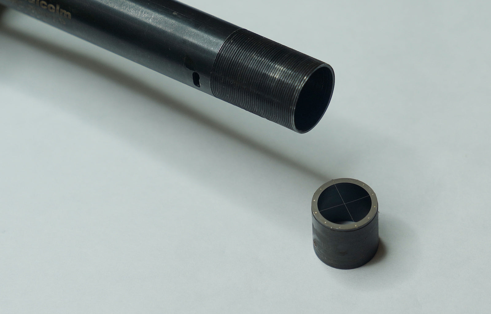
- Ejection guide. This has all the appearance of an oddly bent flat spring. It's actually a surface angled in such a way to bounce empty cases away from the action. This rifle wasn't built with a scope in mind, so the normal ejection path wasn't designed with the sort of low angle a modern rifle would have. This thin metal plate guides empty cases away so that they do not bounce off the underside of the rail and fall back into the action.
- Rear bracket / Clip Guide Replacement. This little part replaces the clip guide that is normally attached above the rear of the action. Removing the clip guide reveals an angled dovetail, which the clip guide replacement will slide into. When the rear bracket is in place, two angled set screws can be tightened to lock the replacement into the dovetail.
- Front bracket. On the left side of the receiver (forward of the ejection port), you'll find a threaded hole. This hole is where the main attachment screw of the front bracket will find its home. Below the threaded hole is a long sort of trough. A small lip that protrudes from the front bracket is meant to fit into the slot on the receiver for alignment.

Installation Steps
The M14/M1A rail kit is quite straightforward, and will take you less time to install than it will take to read this article. There's a bit of wiggle room in the order of steps, so I'll break this into sets of steps.
Preparation
Before the rail can be installed, the rifle and the rail must be made ready.
On the rifle's side, this is easy with the right tools. All you really need to do is remove the clip guide from the rifle (if one is installed). To remove the clip guide:
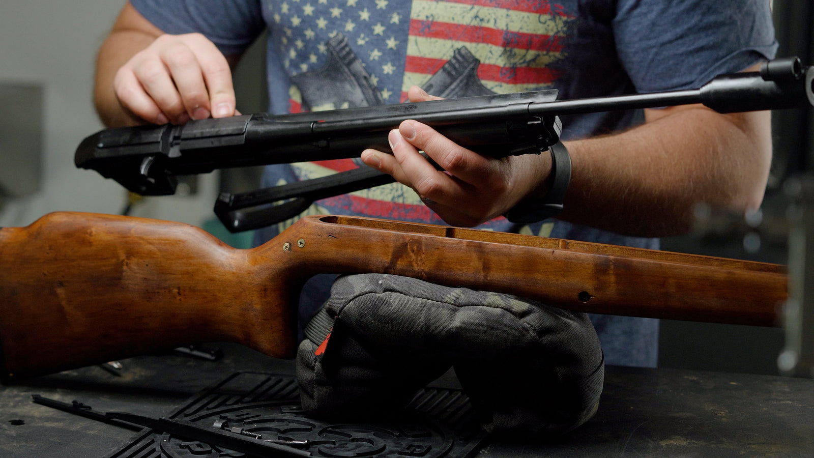
- Remove the action from the receiver. This is done by pulling the trigger guard away from the trigger, which unlatches the entire structure. Once the trigger group is detached, the stock and action should simply fall apart.
- Knock out the pin holding the clip guide in place. This is found on the underside of the receiver, towards the back. There should be a 5/32" hole leading from the underside up to the clip guide at a roughly 45 degree angle. Place your punch in here and hammer lightly. The pin will soon fall out. With the pin out, turn the action upright and tap the clip guide to the left to make it slide out of the dovetail.
- Reassemble the rifle. Drop the action into the stock, flip the pair over, drop the trigger group back into place. If everything is aligned, closing the trigger guard back into place should re-engage the lock.
Preparing the mount is even easier. When the mounting kit is shipped, all the parts are attached to each other. To detach them, remove the two large screws that are countersunk into the top of the picatinny rail. This will separate the kit into four key components: rail, ejection guide, clip guide replacement, front bracket.
To ensure that the clip guide replacement remains in once piece, I would recommend tightening the two windage-adjusting set screws on the left and right sides of the rear bracket. This last step is not strictly necessary, but it helps keep the rear attachment point in place.

Attach the Brackets
The clip guide replacement slides into the dovetail that formerly housed the clip guide. Get it roughly centered, then tighten down the two angled set screws. Once tight, they lock the rear bracket into place.
The front bracket uses the hole on the left side of the receiver as an attachment point, and the trough just below that as a guide. Line up the projection on the front bracket with the trough on the receiver. Slide the bracket forward and backward until the through-hole lines up with the hole on the receiver. Install the screw.
The front bracket can be trued up or tightened in place using the two larger set screws. One is on top, one is on the left (near the main attachment screw). Each of these set screws are locked in place by a smaller set screw, which will need to be loosened when adjusting the main set screws.
Finish Assembly
With the two attachment points in place, there are only two pieces left to attach.
First, drop the ejection guide into place. The angled protrusion should be pointing downward, and should be at the front of the action (closer to the muzzle than to the shooter). Its holes should line up with the holes on the brackets. On top of this, place the Picatinny rail. It should likewise line up with the holes on the brackets and the ejection guide.
Slip the two main screws into place and tighten them down. The assembly is complete.
Notes

External Windage
This bracket provides two key opportunities to adjust external windage. Each has its pros and cons.
As a first note - the two mounting points for the Picatinny rail are 2.755" apart. This means that a movement of 0.0008" (that's 8 tenths of 1 thousandth) is an adjustment of 1 MOA. We're working with very small numbers here.
- Coarser adjustments can be made by moving the clip guide replacement in the dovetail itself. The dovetail cut in the rifle is 1.055" wide, and the bracket is 0.972" wide. This leaves 0.083" of movement, or 103 MOA of adjustment (~51 MOA each side of center). The rail will need to be removed in order to access the set screws holding the clip guide replacement in place. With the set screws loose, the bracket can be moved. Please re-tighten the set screws before attaching the rail.
- Precise adjustments can be made using the set screws to the left and right of the clip guide replacement. The Picatinny rail does not need to be removed for this adjustment to be made. Loosen up the set screw on one side, then tighten the other side to chase it. This will push the attachment point to the left or right, moving the rail itself. The bracket's built in external windage allows for 150 MOA of adjustment (75 MOA left or right of center). The set screws are M5 size, with a thread pitch of 0.8mm (0.0315"). Each full turn of a set screw yields 39 MOA of adjustment.
An important rule to remember: Move the rear in the direction you want the impact to go. If you're hitting too far to the left and would like the impacts to move to the right, adjust the rear to the right.
Snugging the Front Bracket
The front bracket has two set screws that can be used to lock it in place even further than the existing mounting screw and trough/lip. One set screw is accessed on the upper surface of the front bracket. The other is located on the left side, quite near to the mounting screw.
*Both of these set screws have smaller set screws to lock them in place. For any adjustment of the larger set screws, the order of operations should be : loosen small locking set screw, adjust larger bracket-locking set screw, tighten small set screw.
Thread Locker
Though not strictly necessary, some Loctite doesn't hurt. I'll start by recommending blue. Red can be difficult to remove, and green is just impossible. Stick to the blue.
The most useful place for any sort of thread locker is the attachment screw of the front bracket. I would recommend adding Loctite before adjusting the positional set screws.
The second best place for any thread locking compound is in the two main Picatinny Rail screws. Though you can add loctite at any time, I would recommend waiting until the external windage is set. There is a possibility that the small windage adjustments can weaken the bonding compound.
If your external windage is set, loctite can be added to the positional set screws. Remove one set screw, add some loctite, then reinstall that one screw. Only after the screw is fully in place, repeat the process on the other screw. This will allow you to add loctite to the windage adjustment screws without changing your windage.
Loctite can likewise be added to the set screws in the front bracket, though the double set screw design makes this wholly unnecessary.


Leave a comment (all fields required)